SwiftUI 之使用 Path 和 Shape 进行形状绘制
了解 Path
在 SwiftUI 中,如果想要绘制线条或者形状,可以使用Path,Path 是一个结构体用来实现2D 形状的绘制。
如果我们想要绘制下面的形状,
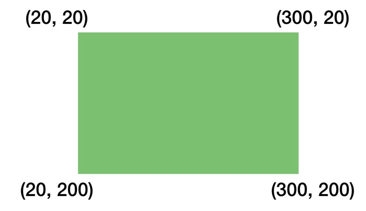
代码如下:1
2
3
4
5
6
7Path() { path in
path.move(to: CGPoint(x: 20, y: 20))
path.addLine(to: CGPoint(x: 300, y: 20))
path.addLine(to: CGPoint(x: 300, y: 200))
path.addLine(to: CGPoint(x: 20, y: 200))
}
.fill(.green) // 填充色
在上面的代码中:
- 使用
move明确形状起点为(20,20); - 使用
addLine绘制点(20,20)到点(300,20)的线 ; - 使用
addLine绘制点(300,20)到点(300,200)的线 ; - 使用
addLine绘制点(300,200)到点(20,200)的线 ; - 使用
fill进行形状的颜色填充。
使用 Stroke 绘制形状边框
有时候,绘制的形状我们不一定是需要完全填充的,我们仅仅需要使用线条呈现出形状即可。这样的效果可以使用stroke修饰器实现。1
2
3
4
5
6
7Path() {path in
path.move(to: CGPoint(x: 20, y: 20))
path.addLine(to: CGPoint(x: 300, y: 20))
path.addLine(to: CGPoint(x: 300, y: 200))
path.addLine(to: CGPoint(x: 20, y: 200))
}
.stroke(.green, lineWidth: 5)
stroke提供了线条颜色和线条宽度两个参数。
此时的效果如下:
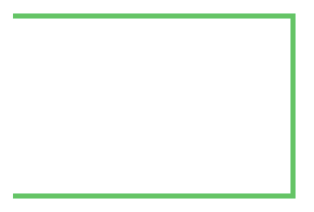
我们会发现此时的形状有一边是缺失的,在使用fill修饰器的时候,因为是整个面积都使用了颜色进行填充,所以我们没有发现这个问题。为什么会出现这样的问题呢,如果我们再去回看我们绘制形状的步骤,我们会发现我们并没有添加点(20,200)和点(20,20)的线。
解决这个问题有两中方法,一是添加回到起点的线:1
path.addLine(to: CGPoint(x: 20, y: 20))
另一种就是使用Path提供了方法,让形状自动闭合:1
path.closeSubpath()
绘制Curves
Path内置的很多 API 可以帮助我们绘制很多的形状,不仅仅是局限于直线。addQuadCurve、addCurve和addArc可以帮助我们绘制曲线和圆弧。
如果我们想要绘制下面的形状效果,就可以使用addQuadCurve方法,这个方法需要两个参数锚点和控制点。
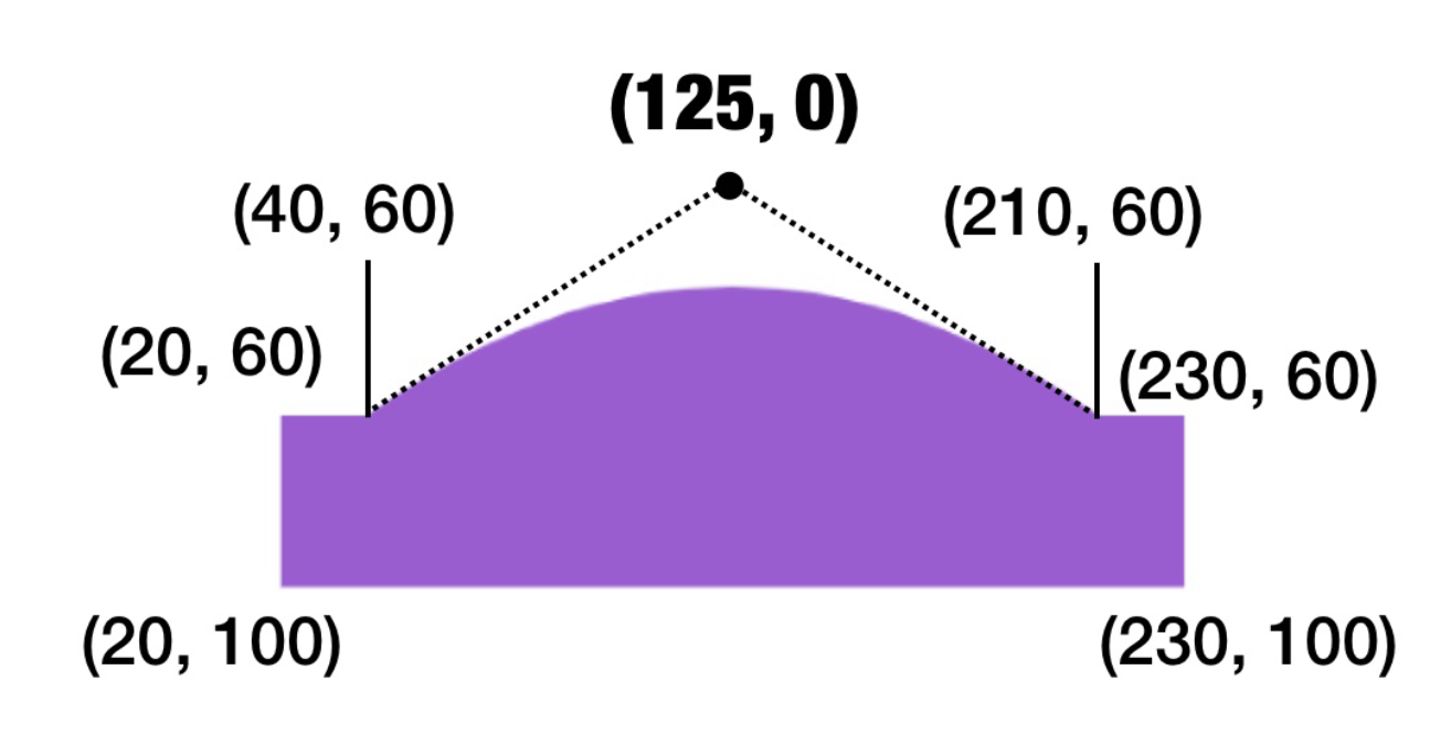
针对上面的曲线部分,它有两个锚点,分别是(40,60)和(210,60), 它的控制点是(125,0)。当然,控制点是不是固定的,我们可以通过调节控制点的坐标来实现不同的曲线效果。1
2
3
4
5
6
7
8
9
10Path() {path in
path.move(to: CGPoint(x: 20, y: 60))
path.addLine(to: CGPoint(x: 40, y: 60))
path.addQuadCurve(to: CGPoint(x: 210, y: 60), control: CGPoint(x: 125, y: 0))
path.addLine(to: CGPoint(x: 230, y: 60))
path.addLine(to: CGPoint(x: 230, y: 100))
path.addLine(to: CGPoint(x: 20, y: 100))
path.closeSubpath()
}
.fill(.purple)
绘制圆弧和饼状图
如果我们想要绘制圆弧或者饼状图,可以使用addArc方法。addArc方法需要多个参数,包括中心点、半径、开始角度、结束角度以及绘制方向。1
2
3
4
5Path() { path in
path.move(to: CGPoint(x: 200, y: 200))
path.addArc(center: CGPoint(x: 200, y: 200), radius: 150, startAngle: .degrees(0), endAngle: .degrees(60), clockwise: true)
}
.fill(.green)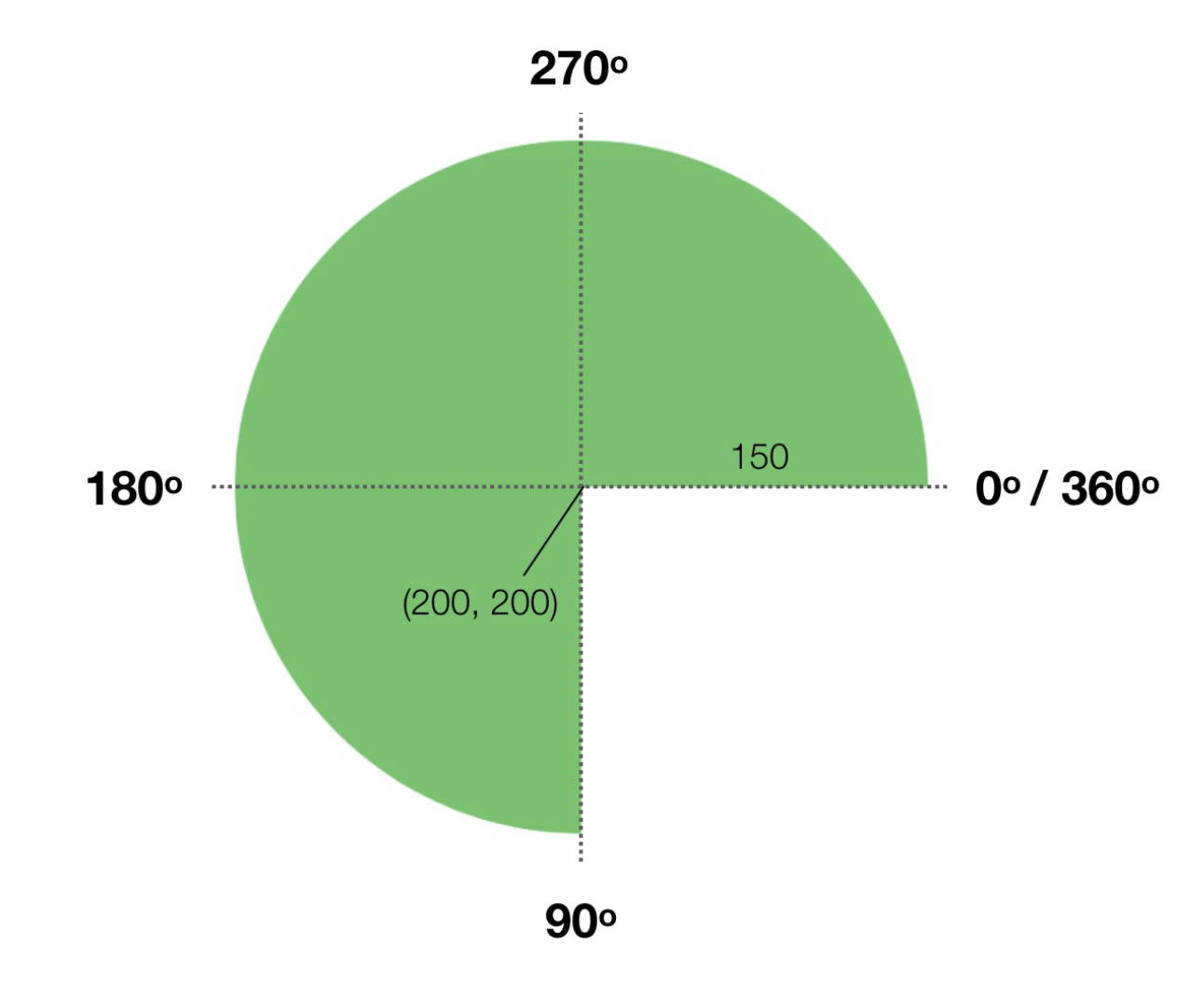
使用形状创建一个进度条指示器
首先,使用LinearGradient定义一个渐变色:1
2
3
4
5
6// 进度条渐变色
private var purpleGradient = LinearGradient(gradient: Gradient(colors: [
Color(red:207/255 , green: 207/255, blue: 207/255),
Color(red:107/255 , green: 116/255, blue: 179/255)
]), startPoint: .trailing, endPoint: .leading)
使用内置形状Circle绘制一个圆:1
2
3Circle()
.stroke(Color(.systemGray6), lineWidth: 10)
.frame(width: 300, height: 300)
接着,在灰色圆的上面再添加一个使用渐变色定义的圆:1
2
3
4
5
6
7
8
9
10
11
12
13
14
15
16
17Circle()
.trim(from: 0, to: 0.85) // 从起点裁剪到 85%的位置
.stroke(purpleGradient, lineWidth: 10)
.frame(width: 300, height: 300)
.overlay {
VStack(spacing: 5) {
Text("85%")
.font(.title)
.fontWeight(.bold)
.foregroundColor(.red)
Text("完成度")
.font(.body)
.fontWeight(.bold)
.foregroundStyle(.gray)
}
}
这里,我们用到了trim修饰器,它可以帮助我们定义Circle裁切。
此时效果如下:

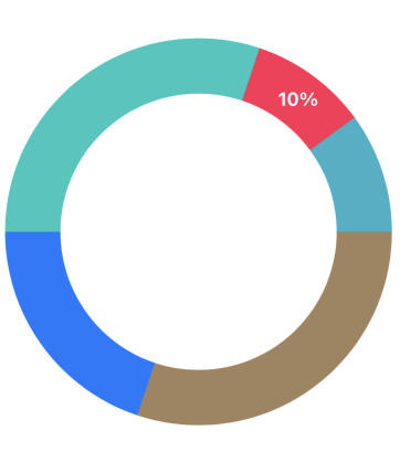
绘制一个环状图
使用上面trim,我们可以使用Circle绘制一个环状图。1
2
3
4
5
6
7
8
9
10
11
12
13
14
15
16
17
18
19
20
21
22
23
24
25
26
27
28
29
30
31
32
33
34
struct ContentView: View {
    var body: some View {
        ZStack() {
            Circle()
                .trim(from: 0, to: 0.3)
                .stroke(Color(.systemBrown), lineWidth: 50)
            Circle()
                .trim(from: 0.3, to: 0.5)
                .stroke(Color(.systemBlue), lineWidth: 50)

            Circle()
                .trim(from: 0.5, to: 0.8)
                .stroke(Color(.systemMint), lineWidth: 50)

            Circle()
                .trim(from: 0.8, to: 0.9)
                .stroke(Color(.systemPink), lineWidth: 50)

            Circle()
                .trim(from: 0.9, to: 1)
                .stroke(Color(.systemTeal), lineWidth: 50)
                .overlay {
                    Text("10%")
                        .offset(CGSize(width: 90, height: -120))
                        .fontWeight(.bold)
                        .font(.headline)
                        .foregroundStyle(.white)
                }
        }
        .frame(width: 300, height: 300)
    }
}
效果如下: